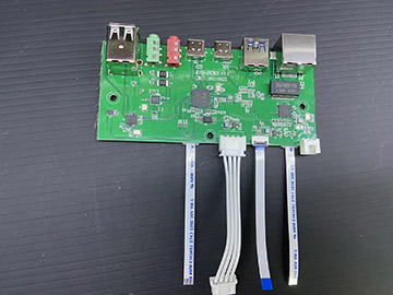
Surface mount technology (SMT) is the process of constructing electronic circuits, in which components are directly welded to the surface of a printed circuit board (PCB). Within the technical scope, surface mounting has replaced through hole technology. The method used in the process of installing the components with cables into the holes on the PCB board and passing through the board from the other side of the board.
What is Surface Mount Technology (SMT)? What are the advantages and disadvantages?
SMD technology is different. The connection is made through the contact on the bottom of the circuit board - the metal terminal around the circuit board. Both technologies can be used on the same PCB for non SMD components, such as transformers and high-power semiconductors in heat sinks.
SMT components or SMDs (surface mounted devices) are typically smaller than through hole technology because they have smaller cables or no cables at all. It can include electronic pins or wires of different shapes, flat contacts, tin ball arrays (BGA ball grid array Aray connection) or metal terminals at the circuit edge. Obviously, it is difficult to assemble parts manually using SMD technology, which is why it needs automation, such as in large-scale production lines. It is a very delicate technology to make SMD design work well even in the environment with high electromagnetic interference rate. Many terms are used in surface technology, and their English acronyms are more familiar:
The following are SMT terms
SMD patch
Surface mounted equipment (active, passive and electromechanical components)
SMT mounting machine
Surface mounting technology (assembly and installation technology)
SMA
Surface mount assembly (module assembled with SMT)
SMC
Surface mount components (components for SMT)
SMP
Surface mount "package" (SMD enclosure form)
SME
Surface mounted equipment (SMT assembly machine)
What are the advantages and disadvantages of SMT in printed circuit manufacturing?
Benefits: Surface mount has many benefits. First, the components are small, for example, in 2012, the smallest component was 0.4 x 0.2 mm. There is also a better component density, which means that there are more components per board area (each component also includes more cables). SMT technology can improve mechanical properties under vibration conditions. Lower initial cost, cost, and production time - and many surface mount parts cost less than the same parts in the through-hole assembly.
More benefits related to assembly. During PCB manufacturing, you do not need to drill so many holes. Automatic assembly is faster and easier; Because some machines can install a large number of components in a short time (130000 components per hour). Similarly, if there are any errors in part placement, these errors are automatically corrected because the stresses in the fusion weld pull the part and realign it with the welding electrode. Another advantage is that components can be mounted on either side of the printed circuit. The low resistance and inductance of the connection reduce the unwanted RF (radio frequency spectrum) impact and provide better, more predictable high-frequency performance. In a word, PCB made of SMT has better EMC (electromagnetic compatibility), that is, less radiation is generated due to reduced radiation space (due to smaller package) and minimum wire inductance.
On the other hand, SMT has some obstacles: for example, due to the reduced size and location of many SMDs, prototype assembly or component level maintenance is more difficult, requiring more personal skills and expensive tools. In addition, surface mount devices cannot be used with bread boards. They need to customize PCBs for each prototype, or install devices on carrier pins with leads completed. For prototypes on specific SMD components, a "branching" board can be used. In addition, strip type prototype plates can be used, some of which include electrodes for standard size SMD components. For prototype manufacturing, a manufacturing method called "dead bug" can be used (this process has a lot of information, but it is in English).
The soldered connections of surface mount devices may be damaged by the thermal cycle of the potting compound. With the development of superfine manufacturing technology, the welding size of SMT joints is rapidly shrinking. The reliability of solder joints becomes more and more consistent, and each solder joint allows less and less solder. When we reflow solder paste in SMT applications, voids are a solder joint related problem. The existence of these "zeros" will weaken the strength of the alliance and eventually lead to the failure of the alliance.
SMT is not suitable for and is not suitable for large parts, high power or high voltage - such as places with high power circuits. SMT and through-hole technology are usually combined with heat sinks, large capacitors, guns, high-power transformers and semiconductors in connectors. Finally, SMT technology is not suitable for connecting components subject to mechanical stress, such as connectors for interfacing with frequently connected and disconnected external devices.


